Saturday, April 15, 2006

WX175 Construction Notes

This supplements the designers construction instructions.

I prefer to build a bit and then test everything to ensure I have not messed up. When things do go wrong step back take a short break. Compare your work to the provided diagrams. look for solder bridges or misplaced wires. That will solve more then 90% of the problems.

For this project first get hyterminal working with a loopback setup. Then build the RS232 setion of the project and get it working in a loopback manner. The build the processor section and get it working. Then connect the processor section to the RS232 section.

Step1: Setup hyperterminal and the serial port cable.
First grab a PC (an old one if you are new to this) and run hyperterminal. Create a connection that uses port1 (or port2) with None-8-1 and no flow control (as described by designers docs). Attach a RS232 cable to that port. Get a DB9 connector of the sex that plugs in the free end of your cable. Jumper pins 2 and 3 together on the DB9. With the jumpered DB9 installed you should see the characters you type echo on the screen. Remove the DB9 and they should stop echoing. Once this works you are ready to start building the kit. Note: be careful not to short pins 2 or 3 to (ground) pin 5. It may blow the RS232 level shifter on your PC.

Remove the jumper from pins 2 and 3 of the DB9.

Step 2: Build the RS232 section.
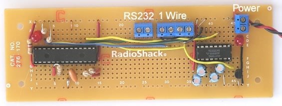
Start with the max232 chip. Add the capacitors and the lines to your DB9 connector. Then jumper between pins 11 and 12 on the max232 chip. This will create a loop such that any characters recieved by the max232 are transmitted back to the PC. Hook the DB9 to a PC serial port. Run hyperterminal as in step1. If you have everything right you will see the characters you type echoed on the screen. Then turn off the power to the max232 and the characters should stop echoing.

Remove the jumper from pins 11 and 12.

At this point we know that the RS232 section works.

Step 3: Build the processor section.
Add the processor (or socket), resonator, activity LED, 6 pullup resistors, and the 4 lines for power and ground. Insert the processor if socketed. Apply power, the activity LED should blink every few seconds to indicate the processor is running.

Step 4: Connect the processor to the max232 chip.
Connect the processor to the max232 chip as indicated in the diagram provided with the kit. If all is well you can send command to the processor and see responses as in kit instructions. Not much can go gone wrong. You tested the RS232 section and only made 4 more connections. Check them if the processor does not respond.

Step5: Connect I/O
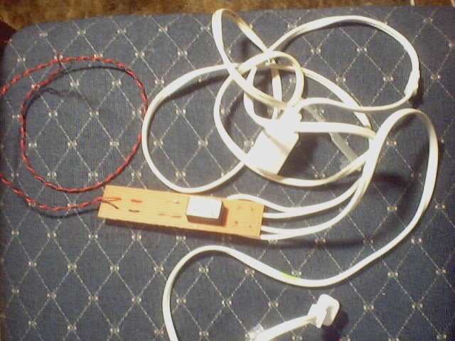
From here on in you are on your own. Hook up a few lines and then test to see if you 'broke anything' and if the new connections work as expected. Maybe start by adding the lines for the 1 wire runs. Then hook up a few temperature sensors.

Good Luck.

Control using an electronic relay.

The intent is to not only monitor, but to control. I dug a 20 year old electronic relay out of my junk box, added a resistor, diod, and extension cord. The hot side (small lug on plug) is split and attached to the power lugs of the electronic relay. The control side will attach to one of the WX175 TTL outputs.


The 3 amp 'relay' I used is out of production, when I find a replacement I will provide more detailed info. I do not want to send anyone off searching for an obsolete part. The diod is there to protect the optoisolator in case the control lines are reversed. It happens.

To test the unit I plugged my desk lamp into the extension cord, plugged the extension cord into the wall, and then applied 5v to the control side of the relay. The desk lamp lit.

The photo to the right shows the actual test. The unit is hiding inside the 2 1/4 PVC pipe with the extension cording protruding from the fron. The power supply just above it is providing the 5 volt signal voltage.

The unit needs an enclosure. I may drill a few holes in the PVC pipe for cooling, add a pair of caps and call it good.

This unit will be used to control the greenhouse cooling fan. The actual hardware will be safe in the garage with the output AC run from the garage to the greenhouse.

More to come...

Intro to the WX175 Weather Station Kit

I was looking for a way to monitor and control the conditions in my small greenhouse when I found the WX175 Weather Station. This gem features 2 Dallas 1 wire bus connections, a connection for a atmospheric pressure sensor, 2 inputs for humidity, 2 TTL inputs, 2 TTL outputs, and a counter input.

The WX175 Weather Station Kit is available from its designer Peter H. Anderson , Specific detailed information regarding the kit can be found here.

I quote "Kit WX #175 including the programmed Microchip PIC (28-pin DIP), 4.0 MHz ceramic resonator (3-pin SIP), MAX232 and associated capacitors, resistors, 22 awg solid wire, the Morgan Logic Probe and documentation - $24.95."

There is no PC board, sensors, or other input devices.

I first assembled the kit on a solderless breadboard (aka Experimenter Socket, QT socket). I verified that several DS1820 temperature sensors worked on both runs. The TTL input and output was also tested.

The WX175 components were then transfered to a Radio Shack board with the same layout as the experimenter socket.


The unit was moved to the garage and linked with a Windows XP via RS232. The run is about 100 feet of twisted pair phone wire (not cat5 which would have been better). I currently have 4 sensors working. The first sensor mounted on the PC board. The second monitors greenhouse air temperature. The third monitors the water temperature in the greenhouse pond, and the fourth measures outside air temperature. The dallas temperature sensors are inexpensive at about $5 each. The WX175 can handle 16 temperature sensors per run for a total of 32.

The designer provides a weather station interface written in Liberty Basic. Because my application was somewhat different I opted to write my own interface. To make things interesting I opted to use a language that was new to me. C# Clicking on any image will provide a larger, more readable view.


I am in the process of writting a C# program (WX175.cs) that sends commands to the WX175 and then displays and logs the results to a linux mysql server. A second C# application (WX175_GRAPH.cs) uses the data on the server to create graphs. The graph below show about 12 hours of somewhat corrupted data I have collected during development.


Both programs require more work prior to publishing but are at least limping at this time.